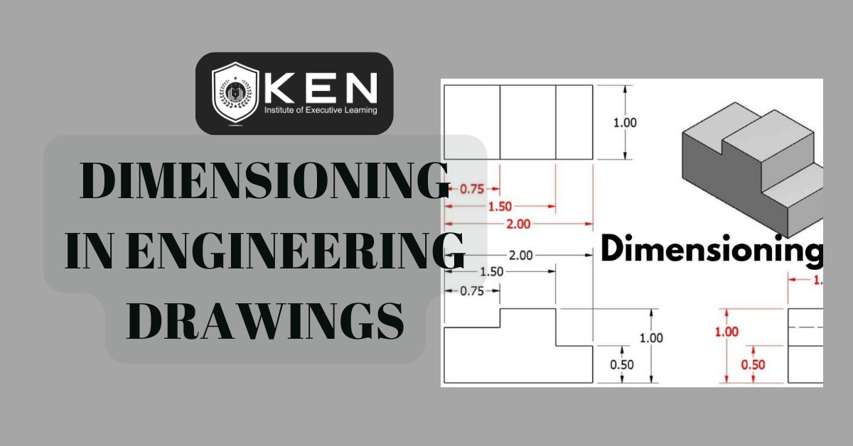
“Dimensioning” in engineering drawings are numerical values indicated graphically in a proper unit of measurement on engineering drawings with lines, symbols, and notes. These are indicated on the engineering drawing to define the size characteristics such as length, height, breadth, diameter, radius, angle, etc. Dimensioning Drawing provides complete shape description and furnishes information regarding the size and description. These are provided through the distances between the surfaces, location of holes, nature of surface finish, type of material, etc. You can create dimensions for existing entities by selecting them, or you can create dimensions by selecting points within a drawing.
Five Basic Types of Dimensioning In Engineering Drawing
- Linear 2. Angular 3. Radial 4. Diametral, and 5. Ordinate.
Dimensions are classified into:
- Functional dimension (F) ñ – A dimension that is essential to the function of the part.
- Non-functional dimension (NF) ñ- A dimension that is not essential to the function of the part.
- Auxiliary dimension (AUX) ñ – A dimension given for information purposes only. It is enclosed in parenthesis and no tolerance applies to it.
Elements of Dimensioning
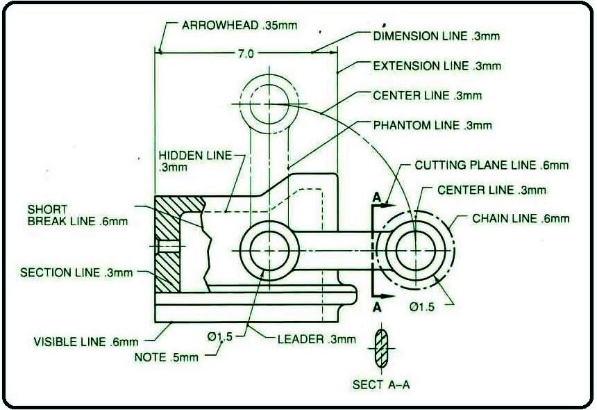
The elements of dimensioning include the projection line, dimension line, leader line, dimension line origin indication, its termination, notes, dimension, etc.

Principles of Dimensioning
Some of the basic principles of dimensioning are:
- All dimensional information necessary to describe a component clearly and completely shall be written directly on a drawing.
- Each feature shall be dimensioned once only on a drawing, i.e., the dimension marked in one view need not be repeated in another view.
- Dimension should be placed on the view where the shape is best seen
- As far as possible, dimensions should be expressed in one unit only preferably in millimeters, without showing the unit symbol (mm).
- As far as possible dimensions should be placed outside the view.
- Dimensions should be taken from visible outlines rather than from hidden lines.
- No gap should be left between the feature and the start of the extension line.
- Crossing of center lines should be done by a long dash and not a short dash.
Execution of Dimensions
Projections and dimension lines should be drawn as thin continuous lines. Projection lines should extend slightly beyond the respective dimension line. Projection lines should be drawn perpendicular to the feature being dimensioned. If the space for dimensioning is insufficient, the arrowheads may be reversed and the adjacent arrowheads may be replaced by a dot. However, they may be drawn obliquely, but parallel to each other in special cases, such as on tapered features.
Dimensioning in Narrow Spaces
A leader line is a line referring to a feature (object, outline, and dimension). Termination and Origin Indication Dimension lines should show distinct termination in the form of arrow heads or oblique strokes or where applicable an origin indication Leader lines should be inclined to the horizontal at an angle greater than 30°. The leader line should terminate
- with a dot if it ends within the outline of an object.
- with an arrowhead, if they end on the outside of the object.
- without a dot or arrowhead, if they end on a dimension line.
Dimensioning of Radii
When a radius is dimensioned only one arrowhead, with its point on the arc end of the dimension line should be used. The arrowhead termination may be either on the inside or outside of the feature outline, depending on the size of the feature.
Methods of Indicating Dimensions
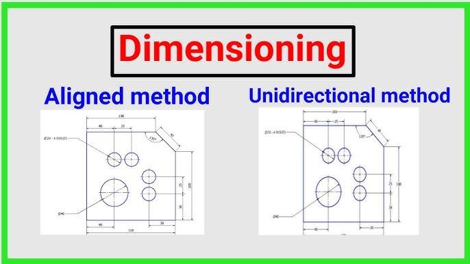
- Aligned method- Dimensions should be placed parallel to and above their dimension lines and preferably at the middle, and clear of the line. Dimensions may be written so that they can be read from the bottom or from the right side of the drawing.
- Uni-directional method- Dimensions should be indicated so that they can be read from the bottom of the drawing only. Non-horizontal dimension lines are interrupted, preferably in the middle for insertion of the dimension. Horizontal dimensional lines are not broken to place the dimension.

Identification of Shapes
The indications that are used with dimensions to show applicable shape identification and to improve drawing interpretation: The diameter and square symbols may be omitted where the shape is indicated. The applicable indication (symbol) shall precede the value for dimension.
Arrangement of Dimensions
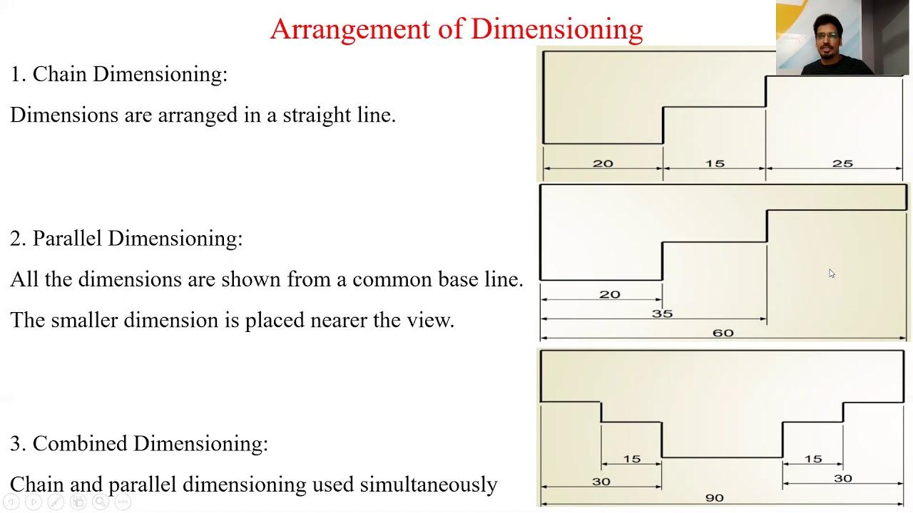
The arrangement of dimensions on a drawing must indicate the purpose of the design of the object. They are arranged in three ways. 1. Chain dimensioning 2. Parallel dimensioning 3. Combined dimensioning.

- Chain dimensioning- A chain of single dimensioning should be used only where the possible accumulation of tolerances does not endanger the fundamental requirement of the component.
- Parallel dimensioning- In parallel dimensioning, several dimension lines parallel to one another and spaced out, are used. This method is used where a number of dimensions have a common datum feature.
- Combined Dimensioning- In the combined type of dimension, the dimensions are arranged in a straight line as well as parallel to each other. It depends on the convenience of dimensioning and the important dimensions. When more than two dimensions overlap, combined dimensioning is done.
“If a part is dimensioned properly, then the intent of the designer is clear to both the engineers, making the part, and the inspector checking the part.”
“Join Ken Institute for comprehensive Mechanical Engineering Courses led by expert faculty, ensuring your readiness to tackle workplace fire emergencies effectively.”
join us at info@keneducation.in
visit our website at www.keneducation.in
or call us at +917569034271
Let’s connect on Facebook, YouTube, LinkedIn, and Instagram.

